Wednesday, June 30, 2010

3D Printing and Part Orientation

I don’t get this question too often but frequently enough where I thought it would be good to give my view on the subject. The question is how should I orient my part in the build? The answer, of course, is that it all depends on what you are trying to achieve. Like all additive processes, 3D printers build one layer at a time. No matter how thin that layer is there is usually some evidence of that line left in the part as it is removed from the printer. Secondary processes can often eliminate the visible effect of layers but with most technologies there is a slight reduction in strength along the Z axis. Visually, on vertical walls this might look like tiny horizontal lines. On curved surfaces it might look like steps along the curvature or arc. With .004” layers the cosmetic effect is very slight. Larger layer thicknesses are more apparent. Thinking about your specific part and armed with this knowledge you can select an orientation in the build area that will minimize the impact to cosmetics and strength. Another consideration is build time. If you want to print something with the shape of a pencil or a ruler you might want to lay it down so that the least number of layers are required for printing. If you were to stand an eight inch long pencil up on end such that the eraser is printed first and the tip last, 2000 layers would have to be printed to complete the build. Laying it down along the X axis would require only 60 layers if the pencil is .24 inches in diameter. Even though the printed area is much larger per layer in this orientation the printing speed makes up for the time it takes to prepare each next layer.


One reason A ZPrinter® is fast is because it prints up to a half inch stripe at a time. This means that in almost any orientation you can print your parts fast. But if you understand part orientation you can maximize the speed and the quality of your build. In general the fast axis, or the direction the carriage moves in, is the fastest. The slow axis, or the direction the entire gantry moves in, is a bit slower. And, the Z axis is the slowest. In addition, the fast axis does not have to travel the full length of the gantry. So if you move your part to the edge of the build where the fast axis starts printing your part will print even faster. In other words, if the printer you are using has 10 inches of travel in the fast axis but your part is only 2 inches long, the carriage will only move as far as it has to in order to print the part. If you position the part in the center of the build area the carriage will have to travel 7 inches to start the fist stripe. For some parts the difference in print speed might not be noticeable but for a 2000 layer build the added time per layer accumulates and could be significant.

The main point is that by knowing how your printer works you can optimize your results and be more successful using your printer. A slight adjustment to your part orientation in the build area can result in significant improvements.


http://www.zcorp.com/

Wednesday, June 23, 2010

Setting Your Monitor to sRGB for 3D Printing

This week's guest post is by Jeff Cunningham, Senior Color Scientist at Z Corporation. In the past, Jeff has worked for the color management company Monaco Systems (now X-Rite) and the inkjet proofing company Iris Graphics (now Kodak), making Z Corporation’s full-color, 3D printing technology the perfect fit.

3D geometry can come from a variety of sources, from 3D scans of real objects to original digital works created on the computer. Wherever the source, the last rendering of the part we see before printing is on-screen, via ZPrint. Computer monitors and printers simply cannot create the same range of colors, whether the printer is 2D or 3D. For instance, printers can jet mixtures of yellow that you’ll never see on the computer screen, while monitors have a huge range of deep blues that won’t make it to paper or powder.


ZPrint does its best to compensate for this disparity of color performance between screen and print. Along the way it needs to make some assumptions, such as ‘what do the colors in this part look like on screen?’ ZPrint doesn’t know if you have an old, burnt-out CRT or cutting-edge RGB LED 10-bit LCD. Other applications ask themselves the same question when you’re looking at family photos or ordering clothes online. To address this problem, HP and Microsoft proposed a model based on “typical” monitor color performance – a standard assumption for applications, operating systems, and printer drivers to use. This model is called sRGB, and when in doubt, ZPrint is to assume that any color defined in a part should look as it does in the sRGB color space.


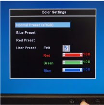
So then, how well does a given monitor match this theoretical sRGB space? It depends on the monitor, of course, but today’s mid-range and up displays can actually match it rather well. They may need to be told to do so though, and each monitor will have a different procedure for changing their color settings. On one random Dell monitor here at the office, it was quite easy. Through the on-screen menu, I only needed to select “Color Settings”, then found “Normal Preset (sRGB)” as the first and default option. You may need to refer to your display’s manual if you can’t find a sRGB option right away.

That’s the quick, easy, and free way to make sure your monitor is doing what ZPrint thinks it should be doing. Since ZPrint targets sRGB colors, this may also help with your screen-to-print color matching. There are more involved methods for calibrating monitors, but they generally require the purchase of special tools for measuring the actual color performance of your display. If color is critical to your application, and you don’t already have a colorimeter, try an Internet search for “monitor calibration”.


http://www.zcorp.com/

Wednesday, June 16, 2010

Adding threads to your parts

Today's guest blogger is Nick Stone, Mechanical Engineer, Z Corporation.

I design a lot of injection molded parts that have threaded inserts or receive self tapping screws. In order to prototype these parts for testing, I print them and install either brass inserts or HeliCoils. Here are some tips on how to use brass inserts and HeliCoils.


Brass Inserts

1. For the brass inserts (known as "threaded inserts for thermoplastics" on McMaster Carr) I drill a hole into the part the same diameter as the thickest part of the insert. You want a nice snug fit so the insert doesn't rotate, but you don't want to be hammering the insert into the part. McMaster-Carr shows a picture with a tapered section to the hole, but don't bother with that; a straight hole works just fine.

2. Thread the insert onto a 1/2" screw so the screw is about flush with the bottom of the insert for easy handling.

3. Coat the outside of the insert with Plastic Welder II. We've tried a few different epoxies and found this one to work the best in pretty much every situation. I'm also a huge fan of this stuff for gluing large parts together that I printed in multiple pieces. Get a bit of the epoxy onto the sides of the hole. Don't overdo it because you don't want to have any of the epoxy get into the insert threads.

4. Carefully push the insert into the hole and use a q-tip to clean off the excess epoxy that squeezes out.

5. If you're installing multiple inserts into the part make sure to have all of your inserts ready and threaded onto screws because the Plastic Welder will start to harden after about 5 minutes.

6. At that point you can carefully remove the screw making sure not to knock the insert out of alignment.

7. After about 20 minutes the Plastic Welder is firm and in 2 hours it's strong enough to install a fastener.

I used this method quite a bit to prototype the structural foam parts for the ZPrinter 650 which I printed on a Z810 in zp130 and infiltrated with ZMax. I've had great success with #8-32 and #10-32 screws. You can use as small as #6-32 but the surface area for glue contact is so little that I found these to be less reliable.

HeliCoil

Since we started using zp131 and zp150, I've moved to infiltrating with Zbond and using HeliCoils for inserts. As far as labor time and effort go, the HeliCoil is equivalent to the brass insert, but I think the final product is stronger and more accurate - plus, you don't have to wait for it to dry. The one downside to the Helicoils is that I haven't had any success trying to use thread locker on the fasteners.

For Helicoils, try to print the hole just slightly smaller than the required drill for the HeliCoil you plan to use. This insures that you'll get infiltrant deeper into the part than the threads will cut. If you have to drill away too much material, you might drill into the internal core of your part, and the coil won't hold as well. I prefer to dip my parts when I infiltrate, so it's a good idea to make sure to dab any excess Zbond that settles into the hole with a paper towel; it'll make drilling easier. The instructions for use are on the HeliCoil box but here they are anyway:

1. Drill out the hole using the recommended bit size.

2. Tap, being sure to go deeper than you need for the HeliCoil height.

3. Insert the HeliCoil and if desired break off the tang using the handy tool.

And that's it. The parts I've made using this technique see much smaller loads than when I used the brass inserts, however I've yet to twist one of these out. The most common mistake is not tapping deep enough, so be sure to do so. If the insert will be installed into a boss, make the boss wall thickness at least .090" in order to avoid having it crack during tapping. Thicker is better of course. With HeliCoils I've gone as small as #4-40 without any trouble.

Everything you need for either technique is available on McMaster-Carr.

http://www.zcorp.com/
Wednesday, June 9, 2010

Comparing 3D Printing and Other Prototying Methods

I read an article in a recent issue of Machine Design.com magazine titled “Rapid prototyping the old-fashioned way” written by Lincoln Charles, an Application Engineer with Phoenix Non-Ferrous Technologies in Franklin, NH. The premise was that there are instances where new technology isn’t always the best suited for your prototyping needs. The method put forth in the article produced metal parts in just a few hours for as little as $35. If that sounds like a great process it actually is. There are many “old-fashioned” prototyping methods that still make a lot of sense. The question every designer needs to ask when looking to prototype a part is which process fits best with my schedule, budget and physical properties requirements? So, the article got me thinking about old-fashioned methods vs. new technology methods and where it’s all going.

I don’t know every prototyping method out there and even if I did there wouldn’t be enough space to print them all here. Old-fashioned methods include metal castings like the one used by Phoenix, Urethane casting, CNC machining, foam core, wood molds, and others. New technology methods include SLA, SLS, 3D printing , Rapid Tooling, and others. With a wide range of options how do you make the right choice for your prototype? It really depends on what is important for that particular prototype. If speed is the most important factor you might pick 3D printing. If material properties are important, e.g. you need a metal part, you might pick CNC machining or casting.

Every method has its limitations. For example, urethane casting and metal casting methods require an element of craftsmanship. The quality of the part you receive is somewhat dependent on the person making the part. SLS equipment is typically very expensive so the option to bring this capability in-house is limited to companies with big pockets and heavy prototyping needs. CNC machining has limitations in creating undercut features and sharp internal corners. The limitations today are pretty much the same as they were 20 years ago. The equipment might be better, faster, or cheaper but you still can’t cut that sharp internal corner. What I like about the new technology methods is the versatility they provide and the ever increasing capabilities. The first SLA parts were brittle and easy to break. Today the parts are much tougher and there is a wide range of materials to choose from. 3D printing methods have made similar strides. Today, 3D printed parts can be used as a mold for casting rubber, urethane, and even metal. The printed part can be the final prototype to be used for functional testing, concept approval, or even as a production part.

Patterns and molds for metal casting, RTV molding and urethane casting applications

Directly print molds, mold inserts and patterns for metal casting

3D printed parts are used for functional testing and production parts
3D printed presentation models are used for evaluating and refining designs, as well as sales and marketing applications

As materials and technology improve, only 3D printing methods seem to have the potential to eliminate many of its current limitations. Wouldn’t it be great if you could design your part without having to consider manufacturing methods, select the material properties you want (glass, metal, plastic, wood), press the print button and have your final part in just a few short hours? Is this capability way off in the distant future?

What I’m curious about this week is what old-fashioned prototyping methods did I miss and which ones do you still use? What is your favorite prototyping method and why?

http://www.zcorp.com

Wednesday, June 2, 2010

George Hart Visits Z Corp.

Guest blog by Dave Russell, Z Corp. Research and Support Engineer, http://www.zcorp.com/

We were pleased recently to host a lunch talk by sculptor George Hart. George is a Research Professor in the Computer Science Department at Stony Brook University where his primary research area is the application of mathematics and algorithmic ideas to sculpture. 3D printing is the ideal way to realize many of his designs, and a large collection of printable files is available on his website.


Before his talk, George laid out a collection of puzzles for everyone to try, ranging from pretty simple to possibly impossible.


He showed a series of short videos of some of his large commissioned pieces, and talked about his practice of involving in the assembly process the community where the sculpture will be installed.

George is currently on sabbatical and talked at length about his work as Chief Content Officer for the new Museum of Mathematics, which will open in New York City in two years. The museum expects 40,000 visitors per year, many of whom will come in school groups. He imagines kids designing parts during their visit and watching their parts being made on site.

http://momath.org/

In response to a question about design software, George said that he primarily uses Mathematica, a general purpose technical computing application from Wolfram Research. Mathematica conveniently offers output in zpr format for 3D printing.

http://www.wolfram.com/

George posts a weekly entry called Math Monday on Make Magazine’s blog. The blog is formatted as a single long page, and finding Math Monday will take some scrolling. You may want to check out the Math Monday archive post entitled Hexagonal stick arrangements (More:).

http://blog.makezine.com/

To see more work of this sort, check out Carlo Sequin’s links:

http://www.cs.berkeley.edu/~sequin/SCULPTS/sculpts.html