Wednesday, December 29, 2010

Color 3D Printing Improves Communication

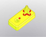
A number of years back I needed to make a simple change to a simple part. The part was injection molded which meant that a change to the part required a change to the tool. Typically, I would send the new STL file to the mold maker and explain the changes in an e-mail. They would plug the STL file into their software, analyze the changes and provide a quote for the modifications. In this particular case I highlighted the changes in red color, printed a model and handed it to the mold maker. Even simple changes to an injection molded part can require complicated tooling changes depending on where cooling lines, ejector pins, rings, and gates are located. Having the actual part with highlighted changes helped the tool maker quickly understand what it would take to successfully modify the tool. A picture of this part, used in our 3D Printers, is shown below.

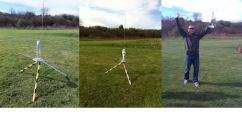
I recently visited a Z Corp. customer who uses a ZPrinter®650 in a similar way. He frequently uses multiple colors to identify different fabrication processes required to complete a part. His parts are complicated shapes from exotic materials. For example, he will highlight the first process with one color, a second process with another color and might add a third or fourth color to show other areas of interest on the part. Because the parts are so complicated and expensive, poor communication can lead to costly mistakes. His main purpose for creating color models is to improve communication throughout the design and fabrication process.

Wednesday, December 22, 2010

Memorable ZPrinted Holiday Ornaments

Every year around this time Z Corporation holds its annual holiday party. It is usually memorable in many ways but one thing that stands out for me is the Z Corp. holiday ornament. David Russell is one of our most senior engineers and for years now he has taken on the task of designing and printing one for every employee. Below is the chronology in pictures. It is interesting to note that over time color was introduced and features became smaller and more delicate as both the hardware and materials technology improved. I want to take this opportunity to thank Dave and I hope this tradition continues for many more years.

2001

2002

2003

2004

2005

2006

2007

2008

2009

2010
Happy Holidays!

http://www.zcorp.com

Wednesday, December 15, 2010

Consumer 3D Printing? Part II

Thanks for the great responses to last week's blog posting: Consumer 3D Printing? I agree with many of the comments. One in particular I agree with is that open source FDM 3D printers are not for the average consumer.

Open source goes a long way toward lowering cost, increasing awareness, and advancing 3D printing technologies. These are all important in order for 3D printing to become a consumer activity.
In my opinion though, in order to break through to this market it must also be fast, have simplicity and elegance. I think of the average person coming home from work (not a technical person) and finding that broken knob on the stove. What would it take for 3D printing to be the preferred method of replacing the knob?

At the very least it would have to be as easy as going to the manufacturers website, picking out the replacement knob, placing an order with a credit card and waiting a few days for the “original” knob to arrive in the mail. 10 to 15 minutes of time online, 2 days waiting, and no technical experience necessary. Open source – and all commercial 3D printers have a ways to go before they can compete with that.

One of the reasons it is difficult to imagine consumer 3D printing is that most everything in the home, office, or car has been mass-produced. That means a tool most likely exists that can turn out replacement parts by the thousands at a very low cost. 3D printing is ideally suited for printing “snowflakes”. The theory is that no two snowflakes are the same. So, if you wanted to produce just a single piece of a one of a kind object would you produce a steel tool and injection mold it?

This is the sweet spot for 3D printing and why it is used for concept models, early stage design verification, architecture, art, low volume prototype parts, etc… Yes, consumers would most likely use a 3D printer to make one or two of any particular part but that part most likely already exists somewhere by the thousands or even millions.

Wednesday, December 8, 2010

Consumer 3D Printing?

A question I get a lot lately is what do you think about consumer 3D printing ? The premise is that someday 3D printers will be as prevalent in people's homes as color inkjet printers are today. Is this far-fetched? If not, how far off is it? And, most importantly, what needs to happen in order for it to become a reality?

The answer isn’t simple. In fact, if there are a dozen or more issues that need to be resolved, the solution for each issue will depend on the solution for the other variables. The first thing you might consider is to lower the cost of a 3D printer to a point where the average consumer could afford one. It might seem obvious that if millions of units are sold every year the cost would come down and be affordable to the consumer. However, if there was a stack of 3D printers on the street corner free for the taking, how many people would take one home with them? And remember, we are talking average consumer, not average design engineer. If they all found homes, what would people print with them? There is no doubt that 3D printers add tremendous value to a commercial enterprise and that color inkjet printers add significant value to most homeowners. But the applications are quite different. The concept that a homeowner would need a 3D printer is based on the idea that they could print final parts at a reasonable cost.

For comparison I’ll use a single part, a control knob for a residential gas stove top. The stove manufacturer would most likely design the knob, prototype it to make sure it looks, feels, and functions correctly. They might even print a tool and cast a limited number of urethane, or metal parts for further evaluation. Once they are comfortable with the design they would order tooling and injection mold the knob using a high temperature flame rated material. Let’s say the homeowner somehow lost the knob for their gas stove top. The first thought would be to use a 3D printer to make a new one. To do so, the homeowner would either have to find or create the 3D data before they could print the part. They would need some type of design software to design a new one. Or maybe they could scan one of the remaining knobs and import the data. But, let’s say there was a database of parts free to download over the internet.

The next step would be to make sure the material properties were adequate for the knob. We know from the application that the material should be high temperature and have a high flame rating – possibly V0. Even if this material existed, the homeowner would have to have it on hand or locate and purchase some. The next part they want to print might require a completely different material. Keeping a stack of document paper and a stack of glossy photo paper isn’t all that difficult, but having all the different materials that might be needed for “real parts” off a 3D printer would be next to impossible for a homeowner. Ordering the right material as it is needed might be the only option. In the time it takes to locate, purchase, setup, and print the knob, would it be easier, cheaper, and faster to order the actual knob from a local stove repair shop?

So, is the idea far-fetched? How far off is it? Weigh in and let me know what you think!

http://www.zcorp.com

Wednesday, December 1, 2010

Six Steps to Assess the True Cost of a 3D Printing System

There’s been a lot of hype over the past year about low-cost 3D printers. All of the rapid prototyping (additive manufacturing) companies have either introduced low-priced systems to the market or lowered the price of existing systems and promote how they are making the technology more accessible to designers, engineers and even the hobbyist. Editors, industry analysts and even the New York Times have jumped on this trend which seems to be the focus of nearly every article and report.

But what is a low-cost 3D printer? When people talk about low cost, they seem to refer only to the purchase price of the 3D printer. Sometimes machines that are billed as low cost are actually much more expensive than most other machines when all variable costs are factored into the equation. We’ve had customers tell us that they purchased another system because of the low initial purchase price of the printer itself, only to quickly discover that they couldn’t afford to keep the system operating. It became an expensive paper weight.

So, how can you cut through the hype and determine the real cost of a 3D printer? Here are six easy steps.

First, let me provide a disclaimer that I’m only referencing industrial- or professional-quality 3D printers. Industry experts seem to universally agree that open source systems that have been receiving quite a bit of publicity recently are not suitable for professional use from a quality, accuracy, throughput or speed standpoint.

1. Yes, affordability starts with a low-priced machine. But look beyond the price of the machine itself. Check to see if the system requires expensive lasers, complex thermal controls or special facility requirements. All of these items can add thousands of dollars onto the price of a machine.

2. How expensive is the build material? Find out how much build material is included in the purchase price of the system. Be sure to base this cost on volume rather than weight (i.e.; how many prototypes will that amount produce?). Then learn the on-going replacement cost of the material.

3. What about waste? Is all of the unused build material from a build completely recycled for future builds and therefore unwasted? If not, make sure you factor the cost of the wasted material into your cost calculator. And, does the system require you to build supports? Some systems require you to build supports, others don’t. Building supports requires expensive build material that can really add up over time, so be sure you factor this ongoing cost into your estimate.

4. What about the cost of post-processing? All prototyping systems require some sort of post-processing. Check to see if you must purchase additional equipment, chemicals, ventilation and special hazardous waste handling and disposal in order to post-process parts. Compare those systems with systems that provide you with the low-cost option to cure parts with tap water and Epsom salt.

5. Assess maintenance costs. Some systems use standard, off-the-shelf inkjet printing technology and a modular design in order to make component replacement quick, easy and cost efficient.

6. Considering all of these variable costs, estimate the total expense per finished model.

Example:
Total cost for Z Corp.’s finished ZPrinted models runs about $2 - $3 USD per cubic in ($0.12-$0.18 USD per cubic cm). An 8.75 cubic in (143 cubic cm) model like the one below costs about $22 USD to produce.

If low-cost 3D printing is important to you, “Buyer beware.”

http://www.zcorp.com  

Wednesday, November 24, 2010

Is 3D Scanning Entering the Consumer Market?

Guest post by Scott Harmon, Z Corp. VP Business Development.

One of Z Corporation’s strengths is that the our technology is based on highly reliable, mass manufactured consumer technology, specifically HP print heads. You would have to be hiding under a rock not to notice that a number of 3D technologies are entering the consumer space. 3D TV’s and movie screens are wide spread, and much has been made of 3D printing kits. But what about 3D scanning? It appears that the time has come.

Many of you have probably heard of Microsoft’s new Kinect. Kinect is a game controller for Xbox, or perhaps the replacement for a game controller. Fundamentally, Kinect can see what you are doing, and it uses your body motion as the interface to games. Technically, Kinect consists of an infrared chip that projects images on a surface and reads them back to determine 3D shape. It also has a camera for capturing color. If you put these together you get a device that can capture color 3D data - for just $150 (USD).

Clearly the data resolution and quality are not going to be anything near what you get with a professional-quality 3D scanner, but at $150, there are going to be a lot more people able to create 3D data very soon. The first hackers have already adapted the Kinect to work on a regular computer and generate 3D data. You can see an example of this at http://www.youtube.com/user/okreylos#p/u/5/7QrnwoO1-8A.

If you know someone who’s creating 3D data using the Kinect, let us know; we’d be happy to make a full color 3D ZPrinted model from the Kinnect data!

http://www.zcorp.com

Wednesday, November 17, 2010

Physical and Digital Prototyping Belong Together

Guest post by Julie Reece, Z Corp.'s Director of Marketing Communications.

Makers of 3D CAD software for digital prototyping sometimes claim that their systems eliminate the need for physical prototypes. However, physical and digital prototyping complement one another. Both should become an integral part of your product-development processes.

In fact, physical prototypes are much in use today because they are essential to creating great designs. Thanks to the speed of 3D printing systems, innovative product developers use more physical prototypes than they did when each prototype was hand crafted, and combine them with digital prototypes to accelerate design.

Digital prototyping tools allow detailed 3D models to be conceived and changed quickly. But computer graphics is no substitute for reality. When combined with additive manufacturing technologies, physical prototypes can be made from digital models quickly and with much less labor than was traditionally required.

Deciding when and how to use physical prototypes in addition to digital prototypes requires knowledge of both digital and physical prototyping methods. Engineering executives and managers need not become additive manufacturing experts. However, they or their designated staff members should familiarize themselves with the various physical prototyping system capabilities, materials, costs, building speeds, and accuracies. With this information, managers will have rational bases for deciding if and when making a physical prototype is more cost effective than analyzing or simulating product behavior with digital prototypes.

Whether you are evaluating physical prototyping technologies in order to purchase a system for your company or employ a service, keep these points in mind:

1. Faster systems with higher throughput to produce multiple models simultaneously are desirable for iterative, conceptual prototypes or visual prototypes that support detailed design, manufacturing engineering, or marketing.

2. If you plan to make many prototypes, low material costs may be more important than buying a low-priced system.

3. Color systems eliminate the need for painting and finishing.

4. Strong but flexible materials may be needed for evaluating snap fits.

5. Some technologies are well suited to making patterns for metal castings while others are not.

6. Higher-strength materials may be necessary for physical testing.

7. Systems with fine surface finish may be required for working prototypes or final advertising shots, but can take longer to produce.

Companies that make wise choices about both digital and physical prototyping technologies will have competitive advantages compared with companies that don’t. The effective combination of both CAD and engineering software with 3D printing and rapid prototyping assures that your company will deliver products that are desirable, affordable, reliable, and safe.

Excerpt of a white paper entitled, “Physical and Digital Prototyping Belong Together,” by L. Stephen Wolfe, P.E.  Read the full white paper.

L. Stephen Wolfe, P.E. is a professional mechanical engineer based in San Diego, California. For more than 20 years, he published the newsletters Computer Aided Design Report, Rapid Prototyping Report, and Product Data Management Report as well as books on these topics. These publications filled the role of Consumer Reports for engineers seeking objective information about product-development technologies. He currently assists buyers of CAD/CAM, CAE, PDM, and rapid prototyping systems with defining their requirements, conducting independent research, identifying and negotiating with suppliers, and implementing new methods efficiently. www.cadcampub.com 

http://www.zcorp.com

Wednesday, November 10, 2010

Engineering Challenge

This week I’m going to write a teaser. Stay tuned for results, pictures, and with luck (edited) video. What happens when a Z Corp. design engineer starts talking about model rockets with other design engineers? Before you know it, custom designed rockets begin to emerge from ZPrinters®! Rockets are not something I spend a lot of time thinking about but the image that comes to mind are of the NASA Mercury and Apollo rockets. They have a nose cone on top of a long cylinder and maybe a set of fins at the bottom. There were a few of those and a few that you would think had no business launching off a pad at a thrust of 10 – 30 Newton. This activity pushed limits of rocket design as well as 3DP capabilities. Simple cylindrical rockets were produced with average wall thicknesses of .025” in order to keep the weight down. More creative designs placed the rocket motor closer to the top instead of at the bottom. Another can be most easily described as a skeletal design having no skin or shell whatsoever.

Challenges like this one help our engineers more fully understand the limits and capabilities of our 3DP technology. They provide a creative environment that fosters problem solving and innovation.

http://www.zcorp.com

Wednesday, November 3, 2010

Iterative Design - As Easy As 1, 2, 3D Print

This week’s guest post is by Leo Kiefer, Z Corporation Mechanical Engineer

I found a good definition on Wikipedia.org the other day:

Iterative design is a design methodology based on a cyclic process of prototyping, testing, analyzing, and refining a product or process.

This could not have described my recent design exercise better.

In an effort to minimize the number of molded parts on a particular 3D printer, I was tasked with the redesign of one of the service stations used in this printer. During the printing process, powder and binder gradually build up on the face of the print head. The role of this particular station is to keep print heads clean by periodically “servicing” or removing the build-up. It is a simple, yet important, process that requires the print head assembly to push down on a spring-loaded cam, set the correct height, and then slide along the cam to perform the proper cleaning procedure.

I was able to consolidate the design into a single injection molded part. I wanted to print a prototype to ensure the design was correct before investing in a molding tool. Due to some design limitations for molding, I was not able to achieve a tight interface between this base part and my cam part. This caused the parts to bind, and not return to their original position in certain scenarios.

Figure 1 - Original model - Shown exhibiting the racking problem and without the rubber wiper.

After some testing and analyzing the cam action, I decided to change the interface to a 2-post and 2-collar design. Essentially the posts would act as guides for 2 collars on the cam part. Since I no longer had to deal with tooling shut-offs in the interface areas, I was able to minimize the draft angles and reduce the amount of clearance between the parts. I retained the single base part requirement, but had to add 2 plastic screws in exchange.

So I printed another model on our ZPrinter® 650. The new iteration did achieve a slight performance increase, but not enough. So, back to the drawing board. I decided to move the bosses further apart, assuming that wider is better, and quickly made yet another 3D printed model. This time I almost had it, but I wanted to make a small tweak in order to get it to be 100% perfect. The binding was completely eliminated in the back to forth direction, yet it still caused problems left to right. Instead of increasing the clearance between my boss and sleeve, I decided to make the holes slightly oval in the left to right direction. Another 3D printed model fresh from the printer proved to have all the requirements I was looking for.

Figure 2 – Cross-sectioned SolidWorks CAD model of final assembly

Admittedly CAD software is a good tool for getting parts to fit together, but when it comes to moving components, nothing beats a good physical prototype. The whole design process could have taken a single day if that was all I was working on, but I was able to cut considerable time off the design process by 3D printing models along the way, versus machining the prototypes. With the help of a ZPrinter, the Iterative Design process is a fast and extremely useful tool in any designer’s bag of tricks.

Figure 3 – Iterative Design summarized in one image

CAD Software: SolidWorks 2010
Printed On: ZPrinter® 650 using zp150 powder
Print Job: 432 layers, approx 2.5hrs

http://www.zcorp.com/

Wednesday, October 27, 2010

Considering Feature Set Value in the Product Development Process

I spend a lot of time thinking about how to enhance our ZPrinter® product line in ways that truly add value to the end user. In fact, when I think about the end user I consider both the person using the printer and the person in need of the printed model. Of course there are other stakeholders but none are impacted by a feature enhancement more than those two. The person who needs the part might be more interested in how fast he can have his model, how accurate the part is, or maybe how close the model’s material properties are to the intended material of the production part. On the other hand, the person running the printer is probably more concerned with ease of use features, such as auto-alignment, cartridge loading, and comfort and visibility while interfacing with the printer.

The design challenge is that often in order to improve one feature, another is impacted. Let me give you a hypothetical example: we might be striving to improve part accuracy, but doing so might slow the print speed. In order to make that decision, we have to understand how to measure the value of further improved part accuracy against reducing print speed to the end user. I would think about this problem in the same way we approach our own product development process where making a single change in a late stage of the process is far more costly than frequent changes in the early stages. Using 3D printing early and often can not only reduce the risk of late stage changes, but will often lead to better decision making and reduced overall cost of development programs. So feature set enhancements that allow for more iterations in the same amount of time and for the same cost are feature sets that add real value.

It doesn’t stop there though. In my example, having more models in the early design stage improves decision making by improving the way the design is communicated. Therefore feature set enhancements that improve the model as a means of communication also add significant value. It is well known that our color printers can be used to create life-like models. Consumer products can be modeled in the intended color combinations or with graphics printed right on the part. Often overlooked is the ability to label models with part and revision numbers or by color coding differences between on model and another, all with the intent to improve and speed up the decision making process.


My question this week is, do you agree with my assessment of value? What do you value in 3DP?

Related reading in Develop3D: http://develop3d.com/profiles/prints-charming

http://www.zcorp.com/

Wednesday, October 20, 2010

Extraordinary 3D Printing

The recent blog written by Z Corp.’s firmware engineer Andrew Berlin about how he used 3D printing in a non-traditional way to encode information  generated a great deal of interest. I think that is fantastic and I am grateful that Andy took the time to write about his efforts. I thought you might want to see a brief video of the ZPrinted record album working. We are working on an audio file, but in the meantime, enjoy the short video

The level of interest his blog generated got me wondering about other “out of the ordinary” ways that 3D printing is being used. For example, there is Enrico Dini who was featured in Popular Science magazine. He believes that someday entire buildings will be “printed.” For now, he is creating large intricate architectural elements that could not have otherwise been created: http://www.blueprintmagazine.co.uk/index.php/architecture/the-worlds-first-printed-building/.

There is also the work being done in Bio-fabrication by Thomas Boland of the University of Texas, Paul Calvert of U Mass. Dartmouth and others. This is a fascinating and diverse field of studies that includes printing biological materials in order to create 3D living tissues. An Internet search will result in pages similar to the following. http://iopscience.iop.org/1758-5090/2/1/010201/pdf/1758-5090_2_1_010201.pdf. This is very far removed from a typical design cycle where 3D printing is commonly used. If successful, this work could lead to 3D printers designed specifically for “building” human organs!

Another example outside the norm is Pixar’s Toy Story Zeotrope. The full color Spectrum Z™510 made this project possible. Because the Toy Story characters were digitally created they were “trapped” inside the computer. Without 3D printing it would not have been possible to accurately translate them from virtual to actual characters. Click the following link for a description of the Zeotrope: http://www.youtube.com/watch?v=ByimDfnq_Fg and click the following link for a higher resolution video of the Zeotrope in action: http://www.youtube.com/watch?v=nKPtmXK--bA&feature=related.

Also check out this YouTube video of two artists who make musical instruments from ZPrinted parts. Audio files and even a music video are currently in development and will be posted when they’re complete.
(Courtesy Elasticbrand [Christie Wright & Arjen Noordeman]
Project: AudioWear
Music by Skooby Laposky
Produced at the new EKWC (European Ceramic Work Centre) CAD/CAM facility, August - September 2010

So, from architectural structures to bio-fabrication to digital arts, new uses for 3D printing are being explored every day. Some are whimsical and some may have very practical applications. Regardless of their utility, what they all have in common is that they have been made possible by 3D printing technologies.

Do you have an interesting, creative use for 3D printers? Let me know about it and I just might feature you here.

http://www.zcorp.com/

Wednesday, October 13, 2010

ZScanning Any Object at Any Resolution With ZScan 5.0

Today's guest post by Julie Reece, Z Corporation Director of Marketing Communications

Today Z Corporation announced a powerful 3D scanning software upgrade that makes using our ZScanner® handheld 3D laser scanners even faster and easier than ever.

What does the new ZScan® 5.0 release (available October 20) mean for you? In a nutshell:

• Scan any size at any resolution within the scanner’s range; no more restraining bonding box

• Merge scans in a single accurate and optimized mesh without any post-treatment

• See your entire 3D surface in real time

• Fill holes, filter boundaries, decimate your model and much more!

Scan any part at any resolution, within the scanners’ range, without any limitations due to part size.

In a word: no more scanning volume. As you can see in the image below, the only parameter that you need to choose is the resolution of your scan. Once you select your resolution, you're ready to scan.

For you scanning volume junkies, this option is still available through the Use Manual Reconstruction Volume checkbox. This option also enables clipping planes.
A user or multiple users can merge scans and reconstruct surfaces using different session files.

This interface is used to merge different scans which have been scanned in the same reference model. This is particularly useful when multiple scanners are used for the same scan or when individual session files are too large for the computer on which the scan is located.
It is important to note that the merge of the scans is made on the raw data, so it's not merely stitching STL files. There is no boundary between the different scans and you still benefit from the powerful surface reconstruction algorithms from ZScan® 5.0.

Automatic hole filling.

Filling holes is controlled with a slider in the facets node, just like the decimate triangles or remove isolated patches slider. This tool focuses on smaller holes that can be filled easily and automatically, and does not offer an interactive mode. It eliminates the time-consuming job of cleaning STL files.

Automatic hole filling also accounts for the texture of the scanned object (with the ZScanner® 700 CX) which was scanned but not projected onto the surface. It does not interpolate the texture. Rather, it applies the object’s texture onto the filled hole. The other holes will appear grey, similar to when you scan without the texture of the ZScanner® 700 CX.


 To read today’s ZScan 5.0 press release.

Also, be sure to register for Geomagic’s Points Beyond Tour, free, worldwide conference, training and networking event.

EXPERIENCE tools that are changing the way companies design, engineer and manufacture – faster, better, greener, more customized.

INTERACT with Geomagic developers, expert users and your peers who are breaking down barriers to productivity, innovation and customer satisfaction.

IMMERSE yourself in the new features of Geomagic Studio 12 and Geomagic Qualify 12 with exclusive training sessions and live demos.

TAKE AWAY information, contacts and knowledge that will help deliver you to points beyond your competitors.

Wednesday, October 6, 2010

Timber House

One of the things I love about working here at Z Corp. is when I am able to help someone discover the unique capabilities of 3D printing, specifically how ZPrinting can help solve real problems.

A few weeks back I ran into an old friend, during a wine tasting event at a local vineyard, who I had not seen in many years. As is often the case during these chance meetings, we both talked at length about what we had been up to over the past few years. The last time I saw him I must have just recently started my career at Z Corp. because he seemed to remember me telling him something about models. My friend is a local architect specializing in high-end custom homes.

Like many individual or small firm architects that have been around for a while, this guy hand draws most of his concepts and many of his detail drawings. His early design decision process involves sketching concepts, reviewing them with the customer, and re-sketching until they both agree on what is to be built. This is time consuming and at the end to the day there is always a risk that the sketch did not accurately represent the final building. How close the end product is to what is expected depends upon the quality of the sketches, as well as the customers’ ability to interpret them or to visualize the final building from the sketches.

Recently some of the younger architects working with my friend started using 3D software to turn early concepts into more realistic renderings in an effort to better communicate and make decisions at this early design stage. As luck would have it, they were in the midst of a project with a client where the husband was in the building profession and, because of his experience, could easily interpret drawings. The husband and wife were in disagreement about a particular detail - whether an entire wall in their new great room should be made of stone or just the section above the fireplace. The architect had rendered the room and shown them the renderings on the computer screen, but a decision had yet to be made.

I offered to take the 3D data from their software and print a model for their next client meeting on the following Thursday. I was able to export the 3D data, including texture map images for the wood, stone and other surfaces. I delivered the completed ¼” scale model in full color on Wednesday afternoon. My friend was amazed, his client was amazed, and I was very happy to help. The husband was finally convinced that his wife was right. Through a chance meeting at a local vineyard, I was able to help a friend solve a real issue by improving communication using Z Corp. 3D printing technology.

Click here and scroll to the bottom of the page to see a sampling of ZPrinted architectural models. 

Wednesday, September 29, 2010

Groovy.exe

This week's posting is by guest blogger, Andy Berlin, Z Corp. Senior Firmware Engineer.

3D printing of appearance models is used to convey visual information. For this project, I explored a non-traditional way in which 3D printing could be used to encode information. I wrote a program that converts an audio file into a printable 3-dimensional model that vaguely resembles a record album, and hacked a record player to generate an audible signal from the printed model.

Before getting started, a quick calculation revealed that for the resulting model to reasonably fit on a record player, the audio file would have to have 8-bit sample depth, limited by the .004” Z-resolution of the printer. And to play the record at 45 rpm, the best sample rate I could hope for out of a 10” diameter record would be about 6 kHz. The resolution would suffer even more as the record played, because the samples towards the center of the record are closer together that those near the outer edge. This might work, but it wasn’t going to be high fidelity.

Version 1 of the program created a monochrome .STL file. The outer edge of each groove is smooth, to provide a surface for the tracking needle to ride along. The inner edge contains peaks and valleys which correspond to the audio data.


In version 2, the program outputs a .ZPR file, where each sample is both coded by color as well as height. High amplitude signals could then be lighter color that low amplitude signals, further enhancing the signal for the optical playback mechanism.

Craigslist provided a cheap, hackable turntable. The tone arm was modified to accommodate a 1” tall printed model. A pin replaced the needle to provide mechanical tracking, and an LED and optical sensor, remarkably similar to the LED/sensor module the ZPrinters use for auto-alignment, provided the playback signal.

While this modern version of a 45 may not be directly useful, perhaps it might inspire other creative or other non-obvious uses for 3D printing.

If you’re wondering whether it was a success, well... if you listen really hard and apply the aural equivalent of squinting, you can just about hear over the noise the Beastie Boys belting out a rhyme from the 21 seconds of ‘Time To Get Ill’ that I printed.

http://www.zcorp.com

Wednesday, September 22, 2010

Creating a 3D Printed Rattleback

Today's guest post is by Nick Stone, Z Corporation Mechanical Engineer.

I came across this toy in a science museum gift shop when I was a teenager. It's a simple canoe shaped piece of plastic that performs miracles. It's called a rattleback and it has amazed people for thousands of years.
Spin the rattleback one direction and it just keeps going. Spin it the other way and it slows down starts rocking, and then, as if by magic, turns back the other direction. Start it rocking and it will begin spinning. The magic is in the weight distribution. It causes the rattleback to have a preferred spin direction. If you spin it in the other direction the rotational energy converts to rocking energy and then back to rotational energy in the other direction. And frankly that's the best explanation I can give because I really don't get it. Oh well, it's still a lot of fun.

I've wanted to print one for quite awhile now and after a bit of trial and error I got a shape that works pretty well. The great thing about having a ZPrinter at my disposal is that I can run through revisions so quickly. I'd say I went through 20 different revisions before I was happy with it. Because the strength of zp150 parts is so high, for a lot of the early revisions I didn't bother to infiltrate. I just depowdered, gave it a spin, watched it not spin back, and then tossed it in the trash.

This model is about 4 inches long but I've scaled it up to 26 inches and all the way down to 1 inch. It seems to work better the larger it is. The surface finish is important so after a dip in ZBond 101 I smooth the bottom with fine grit sand paper. I get about a half turn back from the 4 inch version. Let me know if you can beat that.

Here's a video of a 26 inch model we printed on a Z810. It actually shakes the table when it starts rocking.

http://www.zcorp.com

Wednesday, September 15, 2010

Nike's Future Sole Competition

I know Nike uses Z Corporation's 3D printing technology in their shoe development process but I had not heard of their Future Sole Competition. First of all, what a great name for a competition: Future Sole. The name alone makes it worth checking out. The Future Sole Facebook page includes videos, pictures and more. The contest allows high school and college students the opportunity to submit a shoe design to Nike. The designs from each category that make it to the final rounds get to work Nike designers as mentors on a new project. It appears that the final presentation includes a 3D printed model of their shoe printed on a Z Corporation 3D printer. The winners were recently posted on the blog Eastbay.com with photos of the winners, their designs and accompanying 3D printed models. Here's some more coverage of the competition by Sneaker.com. 

What a thrill it must be for a high school or college student to see their winning design as a full size color ZPrinted model. Whether you are into sneaker design or not it’s worth checking out this competition.

http://www.zcorp.com

Wednesday, September 8, 2010

Inkjet 3D Printing or DLP Plastic Prototyping: How to Choose?

In the traditional design process (concept development>detail design>build/test> manufacture/ship) rapid prototyping has historically addressed the build/test and manufacturing/ship phases of the process, providing necessary form, fit and function testing and verification of designs. 3D printing is widely thought to address only the concept development and detailed design phases of the process, enabling designers to iterate more frequently, resulting in greater innovation.

Today, the previously clear lines between 3D printing and rapid prototyping are blurred. In fact, there’s overlap in the testing phase of the process. Z Corporation’s inkjet 3D printers meet the needs of many customers requiring form, fit and functional testing and verification. Z Corp. uniquely provides both inkjet 3D printers and plastic prototyping systems to meet all phases of the design process.

Many people think that they need plastic because that’s what certain manufacturer’s have led them to believe, when in reality, most people don’t need plastic for their applications, and in fact, they could be saving significant time and money using inkjet 3D printing. However there are times when a plastic DLP system is the right tool for the job. So how do you decide which system, inkjet 3D printing or plastic prototyping, is the best tool for your application?

Over the next couple of months our worldwide channel partners are running free, in-person, interactive seminars that will explain and demonstrate how you choose which type of technology is best for your unique application. The “How to Choose the Right Prototyping System” seminars will include live product demonstrations, reviews of applications, analyses of costs, displays of prototypes you can produce with each technology, methods for making smart device choices, interactive Q&As, and even a contest drawing for a Flip camcorder. These seminars are run by experts who will be happy to answer your questions.

I encourage you to take advantage of this great educational opportunity that could ultimately save you a lot of time and money in your job. For more information on the seminars, including locations and dates, visit: http://www.zcorp.com/en/Events/How%20to%20Choose%20the%20Right%20RP%20System%20Seminars/spage.aspx

http://www.zcorp.com/

Employee Appreciation Day

I’m going to change things up a bit this week and talk about a recent company event. Every year in the summer Z Corp. employees spend a day off site at an event call the Employee Appreciation Day. It’s basically a Z Corp. holiday. This year, as in years past, we spent the day at a local private recreation facility that includes a pool, soccer field, volleyball, basketball, mini-golf, and my favorite, batting cages with unlimited pitches.

The day included a continental breakfast and a cookout style lunch. There was no real structure for activities so everyone could migrate to whatever they were most interested in. Throughout the day I would have to say that it every part of the facility was taken advantage of. The food was great and the weather this year was perfect. One of the best things about an event like this other than the fact that we otherwise would have been working hard developing the next big innovation in 3D printing is the opportunity to mingle in a casual non-work environment with people from across the company that you typically don’t interact with on a daily basis.

Z Corp. isn’t the first company that I have worked for that held an event like this. One company in particular used to take the day off, get on a boat, and spend the day at the beach having a lobster bake. But, most have not. What is your experience? Does the company you work for have an Employee Appreciation Day? Let me know what they do and what you think of the event?

http://www.zcorp.com

Wednesday, September 1, 2010

Todd Grimm's June 2010 3D Printer Benchmark Report - Part II: Cost

A few weeks back I posted a blog about Todd Grimm's 3D printer benchmark report. One topic the study covers is cost. It includes the cost of the prototype, cost of acquisition, and cost of operation. I like this topic because there are many variables that impact cost and I assume people place more or less importance on some of these variables. For instance, when considering a 3D printer do you first consider cost per cubic inch or are you more interested in the purchase price of the equipment? Logic says that a savvy buyer will consider the total cost of ownership which includes all costs over the useful life of the printer. Is that really the most important decision when considering cost?

This is an important topic from an R&D perspective because we made design decisions every day that impact these cost variables. Keeping total cost of ownership the same, let's assume that we could decrease the cost per cubic inch of material used to create a model simply by increasing the cost of manufacturing a printer. The total cost of ownership might stay the same but the cost distribution is different. Here's another example. Assume the cost per cubic inch of material used for a prototype can be cut in half simply by increasing the time it takes to produce the prototype by slowing down the printer. Is that a trade-off you would make? Following this a bit further, what cost would you place on the time it takes to print your part if it is entirely hands-off.

In the real world you can't simply add cost in one area to lower cost in another. But you can influence them in one direction or another. So, considering all costs associated with 3DP, which ones are more important to you? If you produce models every day you may be more concerned with the consumable material cost. If you are an infrequent user you might be most concerned with the price of the 3D printer. But, I'm interested in hearing from you and knowing what you consider important.

http://www.zcorp.com

Wednesday, August 25, 2010

The Importance of Prototyping in Education

It’s very satisfying for me to design and develop products that help students learn. Whether it’s our ZPrinters, ZBuilder or another manufacturer’s prototyping system, having students work with rapid prototyping or 3D printing systems in the classroom is invaluable for them to gain a deeper understanding of the design process, to engage them so they are more enthusiastic and excited about what they’re learning and to help them gain a competitive advantage when seeking jobs or higher levels of education. After all, they will be using prototyping systems when they land jobs, so their education isn’t complete unless they work with those systems in school. I’m not just talking about technical universities…high schools, colleges, and vocational schools can and do benefit and, more importantly, benefit their students, by having prototyping systems in the classroom.

It’s incredibly gratifying to have a high school student approach me at a tradeshow (industry tradeshows often set aside a special day when they invite students studying design and engineering to talk to the different manufacturing companies and gather information for a class assignment) and proudly tell me that they use a ZPrinter and even show me examples of the models they’ve printed. They also can’t get enough of the sample 3D printed parts we hand out at the shows! I always ask them what they like best about the particular ZPrinter they have, and they tell me how “cool” it is to be able to print and hold their designs and they love to tell me how easy it is. Students who have a monochrome prototyping system can't believe that our multicolor models on display came out of the printer in full color and weren't painted...that always draws a "Wow! That's so cool!"

I firmly believe that prototyping in the class gives students confidence and a real sense of pride in their design capabilities.

Are you a student or teacher using prototyping or 3D printing in the classroom? How has it helped you to learn or teach design? Do you teach design without a prototyping system? If so, why haven’t you brought one into the classroom? As always, I look forward to your feedback.

http://www.zcorp.com

Wednesday, August 18, 2010

Reverse Engineering Aircraft with 3D Scanners

I’m going to change things up this week. It occurred to me that I haven’t written about 3D scanning yet, and every now and then I like to highlight some of the cool things people are doing with our technology. So this week, I combined both of those ideas.

You probably know that we have a line of handheld 3D laser scanners called ZScanners. One of those scanners, the ZScanner 700 PX, is able to scan very large objects, like airplanes, trains, trucks, buildings… you get the idea. It can do this because AICON photogrammetric software is built into the system.

M7 Aerospace, located in San Antonio, TX, USA, uses this scanner to capture precise, 3D data of entire planes, down to one-thousandth of an inch. Recently they scanned the entire surface of a Fairchild Metroliner in a resolution of 0.1 mm in three days. If you’re not familiar with aircraft, the Fairchild Metroliner is a 19-seat commuter-class, turbo prop aircraft with a 57-foot wingspan. Then the folks at M7 used the engineering data they captured with the scanner to reverse-engineer components that were originally designed during the 2D era (before 3D CAD was readily available) that needed retrofitting and repair.

M7 Aerospace also maintains and modifies legacy aircraft for the US military and foreign governments. They told us that older, yet still viable, aircraft sometimes perform modern roles and need to be modified with ballistic blankets, avionics upgrades and external sensors for missile defense systems. Those types of modifications can be expensive and take an incredibly long time without precise data, which is often missing because the original design documents are gone or because of variations in an aircraft due to factors like wear and tear. The scanner enables them to capture the precise engineering data they need to repair, modify or retrofit any plane they come across and keep a detailed design template for any plane of the same design.

I think this is a pretty interesting use of technology, even if you’re not an aircraft buff. What do you think? Were you aware of 3D scanning? Do you use it yourself and have an interesting story to share? I look forward to your feedback.

http://www.zcorp.com

Wednesday, August 11, 2010

Todd Grimm's June 2010 3D Printer Benchmark Report

Did you catch Todd Grimm's June 2010 3D Printer Benchmark Report? It is available as a free download at http://www.tagrimm.com/benchmark-2010/download_benchmark.html and is pretty interesting reading since it is an independent third party analysis. More about Todd Grimm and his company T.A. Grimm & Associates can be found here: http://www.tagrimm.com/company/index.html along with a number of other industry publications and tools, some free to download and some for purchase.

Like any report of this nature it isn't perfect. For example, the ZPrinter 310 was used for this analysis. If the newer models ZPrinter 150, ZPrinter 250 and ZPrinter 350 were considered instead, some of the results would likely be different. Overall, however, I agree with most of the conclusions in the report. I thought that instead of writing about my views on this paper I would bring it to your attention, give a brief overview, and ask for your opinions and experiences. Do they line up with the conclusions found by Grimm?

It focuses on the fastest growing segment in additive manufacturing – 3D Printing. So, comparisons where made between the six lowest cost printers available from five different manufacturers. As mentioned above, Z Corporations three newest products (ZPrinters 150/250/350) might have been considered if they had been available when the data was collected for the report.

As stated in the report, the purpose of the study was to determine just how fast, inexpensive, and easy to use 3D printers can be. To do so the following four areas where reviewed: Time, Cost, Quality, Operation, along with a number of subcategories. In the coming weeks I will give you some of my insights on cost, part quality and ease of use. But if you will allow me to give you an assignment, download the study, read it (the pictures are nice also), and let me know what you think. Do the conclusions ring true to your experience or assumptions? And, what part of the study is most important to you, cost, ease of use, other?

http://www.zcorp.com

Wednesday, August 4, 2010

ZPrinter Product Differences - Part II

Wow, it was just a few weeks ago I talked about the differences between several of the ZPrinter® products and just last week, we come out with two more! Of course I knew about the planned launch of these new products, the ZPrinter 150 and ZPrinter 250, but couldn’t talk about them at the time. I was quite happy to see several comments from that recent post asking for smaller and lower cost printers. In a nut shell these two new business and industry-quality ZPrinters combine many of the ease of use features that all of our recent printers have to a set of entry level offerings. The idea is to allow customers the option of paying only for what they need. If you are not interested in color and your parts will fit into a smaller build volume, the ZPrinter 150 might be the right choice. It is our lowest cost option. Why pay for more than you need to increase your productivity? For larger monochrome parts you might want to upgrade to the ZPrinter 350 with a slightly better resolution and larger build volume. The difference between the ZPrinter 250 and 450 can be viewed similarly. The ZPrinter 450 has a slightly larger build volume and significantly better color quality than the 250. So, if you primarily have a need for monochrome parts but require color from time to time the 250 is a good choice. For improved color capabilities upgrade to the ZPrinter 450. And of course, for best in class color, resolution, speed and build volume (which often leads to increased productivity) you should consider the ZPrinter 650.

Have you seen these two new products? What do you think? I look forward to your feedback.

http://www.zcorp.com

Wednesday, July 28, 2010

Are Open Source 3D Printers Really Suitable for Business?

I have to make a disclaimer before going further with this blog. Much of what I will write here is my own viewpoint from what I have read or from conversations I have had with others in the field of 3D printing. The topic is open source 3DP. There are a number of FDM (fused deposition modeling) printers available now in “kit” or open source form. This basically means that anyone can search the internet and find all of the components necessary to build their own FDM printer. Some have assembled the components and offer them for purchase as a kit that you assemble. At first I thought this would be a great way for technical schools to teach about using 3DP as a design tool while at the same time teaching about basic electronics, motion control, and programming. But then I started wondering how many times the kit could be disassemble and reassembled as new students enrolled in the appropriate course. Open source clearly is a way to buy into 3D printing technology at a relatively bargain price. Still, the cost is in the thousands of dollars and from what I can gather the printed part quality is not, at present, all that impressive. Layer thickness is about .012 of an inch which means distinct vertical lines throughout the part. Feature size limit is .080 of an inch which means that many small features simply cannot be printed.

In his blog last week, Al Dean of Develop3D had this to say:

“Many have been talking about the mass adoption of 3D printing for some time, but I’m not entirely convinced it’s going to turn into that world where everyone has a 3D printer in their home for a good long while, if at all. At present, there are dramatically lower cost options available, but these are aimed at the hobbiest looking to take on some new technology and give it a whirl. There’s absolutely nothing wrong with that, but when you’re a professional organisation looking to bring your prototyping needs in house, you need something that’s lower maintenance, that produces more repeatable results and that you can get high-level support for when problems occur. Z Corp admitted that its not looking to dramatically erode the price levels rather continuing to lower things gradually as it can conduct cost economics and redesign work to bring the cost down in increments. After all, these products are aimed at professionals, as they most likely will for many years to come, and that means that a robust product that produces the results, is more desirable than chopping the margins out of the machines in a dramatic manner."

Who then is buying open source FDM printers? It isn’t clear to me that there is an industrial, true business application for open source 3DP. Do you agree? Let me know.

http://www.zcorp.com/

Thursday, July 22, 2010

Announcing Two Additions to ZPrinter Product Line: ZPrinter 150 and ZPrinter 250

Today's guest blogger is John Kawola, Z Corporation CEO.

Today I’m happy to announce two additions to our award-winning ZPrinter product line: the ZPrinter 150 (entry-level monochrome) and the ZPrinter 250 (entry-level multicolor). These new affordable, business-class 3D printers make 3D printing available to every designer, engineer, architect and student.


ZPrinter 150                     ZPrinter 250

With a smaller footprint than the rest of our line, these new ZPrinters make great, industrial-quality parts while delivering Z Corp.’s trademark speed and affordability.

ZPrinter 150 monochrome 3D printed model
ZPrinter 250 multicolor 3D printed model (apply text, color, logos)


With our recently announced ZBuilder Ultra plastic rapid prototyping system and our comprehensive ZPrinter product line, Z Corp. uniquely provides a single source for both inkjet 3D printing and plastic DLP rapid prototyping solutions, which means we provide engineers and designers with solutions for all stages of the product design/development process – from early-stage concept modeling through form, fit and functional testing.

I invite you to learn more about the ZPrinter 150: http://www.zcorp.com/Products/3D-Printers/ZPrinter-150/spage.aspx and about the ZPrinter 250: http://www.zcorp.com/Products/3D-Printers/ZPrinter-250/spage.aspx.

Wednesday, July 14, 2010

ZPrinter Product Differences

When we make a decision to introduce a new product, it is important to us to increasingly add value to the customer. But value can be interpreted in many different ways. Sometimes more is less. For example, our entry level and education product is the ZPrinter® 310 Plus. This is a legacy product and does not offer many of the automated material handling capabilities of the ZPrinter 350, ZPrinter 450 and ZPrinter 650. So, what’s the difference?

The main feature categories for our printers are build volume, resolution, and color. There are others of course but let’s focus on these. The ZPrinter 310 Plus is a monochrome printer. It can print almost any color you want but just one color at a time. For instance you can put yellow binder in the printer and print yellow parts or you can mix yellow and cyan and print a greenish color part. By mixing yellow, cyan and magenta you can achieve almost any color of the rainbow.

The ZPrinter 450 introduced automated powder and binder handling. The build volume is the same as the ZPrinter 310 Plus (8”x10”x8”) but the loading of binders and powder is fully automated through the use of cartridges. When the printer calls for more binder the user simply plugs in a new cartridge and the printer is ready to go. Any powder that is not part of the model is automatically recycled back into the printer. The ZPrinter 450 is a full color printer. You can paste a jpg image onto your 3D data and it will be printed directly onto your model. This is any color, on demand, just like your color printer at home but in 3D. Resolution for the ZPrinter 310, ZPrinter 350 and ZPrinter 450 is 300 x 450 dpi. This measurement is similar to a home or office inkjet printer.

Automatic Powder Loading on ZPrinter 450


Model printed on ZPrinter 450

The 450 is a very powerful tool but if you need even better color, resolution and size, the ZPrinter 650 is a better choice. With a 10”x15”x8” build volume, 600 x 540 dpi, and a separate black color channel in addition to yellow, cyan and magenta, this printer offers the best color, resolution and print size, in addition to all of the automated material handling features offered in the ZPrinter 450 class.

Model printed on ZPrinter 650

This is just a quick snapshot of how our ZPrinters differ from one another. I hope it is helpful. As always I am curious about your thoughts. Which product characteristic is the most important to you? If we designed a product just for you would what build size would you want? Would it be a color printer or monochrome?

http://www.zcorp.com

Wednesday, July 7, 2010

Calling for ZBlog Topics

I started this MCAD-focused ZBlog about two months ago and have talked about a wide variety of topics. They range from general topics such as “what is 3DP?” to more specific technical topics such as adding threaded inserts to 3DP parts. We’ve talked about color, the interesting research of George Hart, various uses for 3DP and some of the interesting projects by our R&D staff. The following has been strong and continues to grow which is very exciting. The comments so far have been inquisitive and supportive. When we talked about where to find free 3D model data there were many contributions adding favorite sites to the list.


As we move forward in the coming months we will be talking about many more 3DP topics in the MCAD world. Topics will include various tips and tricks to successful printing, file formats, a look inside the R&D department, guest bloggers and more. As you have probably noticed I end most of my blogs with a question. I think one of the reasons I first became an engineer is because I am naturally curious. I am curious now about what topics you would like us to write about? What are you interested in the most?

http://www.zcorp.com

Wednesday, June 30, 2010

3D Printing and Part Orientation

I don’t get this question too often but frequently enough where I thought it would be good to give my view on the subject. The question is how should I orient my part in the build? The answer, of course, is that it all depends on what you are trying to achieve. Like all additive processes, 3D printers build one layer at a time. No matter how thin that layer is there is usually some evidence of that line left in the part as it is removed from the printer. Secondary processes can often eliminate the visible effect of layers but with most technologies there is a slight reduction in strength along the Z axis. Visually, on vertical walls this might look like tiny horizontal lines. On curved surfaces it might look like steps along the curvature or arc. With .004” layers the cosmetic effect is very slight. Larger layer thicknesses are more apparent. Thinking about your specific part and armed with this knowledge you can select an orientation in the build area that will minimize the impact to cosmetics and strength. Another consideration is build time. If you want to print something with the shape of a pencil or a ruler you might want to lay it down so that the least number of layers are required for printing. If you were to stand an eight inch long pencil up on end such that the eraser is printed first and the tip last, 2000 layers would have to be printed to complete the build. Laying it down along the X axis would require only 60 layers if the pencil is .24 inches in diameter. Even though the printed area is much larger per layer in this orientation the printing speed makes up for the time it takes to prepare each next layer.


One reason A ZPrinter® is fast is because it prints up to a half inch stripe at a time. This means that in almost any orientation you can print your parts fast. But if you understand part orientation you can maximize the speed and the quality of your build. In general the fast axis, or the direction the carriage moves in, is the fastest. The slow axis, or the direction the entire gantry moves in, is a bit slower. And, the Z axis is the slowest. In addition, the fast axis does not have to travel the full length of the gantry. So if you move your part to the edge of the build where the fast axis starts printing your part will print even faster. In other words, if the printer you are using has 10 inches of travel in the fast axis but your part is only 2 inches long, the carriage will only move as far as it has to in order to print the part. If you position the part in the center of the build area the carriage will have to travel 7 inches to start the fist stripe. For some parts the difference in print speed might not be noticeable but for a 2000 layer build the added time per layer accumulates and could be significant.

The main point is that by knowing how your printer works you can optimize your results and be more successful using your printer. A slight adjustment to your part orientation in the build area can result in significant improvements.


http://www.zcorp.com/