Wednesday, June 15, 2011

Are 2D Product Comparison Grids Useful for 3D Printers?

This week’s guest blog is by Julie Reece, Z Corp’s Director of Marketing Communications.

I am not a fan of product comparison grids. I understand that in theory they are meant to make it easy for purchase decision makers to compare competitive products and services in what their authors proclaim to be fair comparisons. You know the kind I’m talking about…they provide a short list of capabilities or criteria down the left column of the grid and various competitive products/services across the top row, and use check marks or some other type of indicator within each box to indicate whether or not that product or vendor offers each listed capability. They’re everywhere – across industries and markets. I remember first seeing such a grid early in my career at a very large software development company, and even used them myself at the time in my marketing role at that company. I haven’t used one since. Recently I've seen product comparison grids authored from reputable, third-party industry organizations and 3D printer manufacturers.

So, why am I so anti-grid? Yes, I’ll admit they bring back vivid memories of my less-than-stellar performance studying charts in high school math class. But more importantly, the validity of the picture grids intend to paint is guided solely by their authors and therefore they inherently come with the author’s bias or, at the very least, assumptions about which criteria is important to include and exclude. And, grids don’t enable product evaluators to assign an importance weight or score to different purchase criteria given differing sets of needs.

For example, if the author comes from one of the competing companies included in the grid, he/she is going to list the criteria where they feel they ‘win’ and conveniently omit criteria where competitors win. Even worse, a chart I recently saw from another 3D printing company contained false information. But if it’s on a chart, it’s true, right? Not necessarily.

You might say, sometimes highly knowledgeable, objective and well-meaning third parties develop product comparison grids. But do they always know all of the important criteria and capabilities to include? One of the industry grids I saw did not include all of our relevant products for the topic, resulting in a slanted picture of the available product offerings. Another grid omitted a few key criteria that purchase decision makers in our industry consider.

Even if the industry-savvy authors include a complete list of evaluation criteria in their grids, how can purchase decision makers prioritize, or assign an importance score to, the criteria within those grids? They can’t. Take 3D printing for example. Every company and department application for 3D printing is unique. Criteria that might be critical to one company or department (things like build size, speed, color, surface finish, materials, printer cost, material cost, method of post-processing, type of material used, office-friendliness, and so on) might be completely insignificant to another. If you’re an educator, low cost of operation, build speed, throughput and safety might be your top priorities and you might be willing to do without color or a specific material property. If you’re a manufacturer of consumer goods, color, speed and low material cost might be your top priorities and you might not be concerned about material properties. If you need flexible, functional parts, then material properties will likely be your primary concern, and you might be willing to sacrifice low cost, color, build size, and so on. The point is there isn’t a nice, neat grid that can address your individual company and application needs.

Careful product evaluation isn’t always easy, but it is critical. So, when you see a 3D printer product comparison grid, be wary. Instead, I encourage you to schedule a personal appointment with representatives from each of the 3D printing companies. Describe your application needs to their representatives and listen to how their solutions can solve your application challenges and open new doors to success. Ask each representative to focus on how their solution can satisfy your application needs. See a demonstration. Talk to their customers. Do your homework. Perhaps create your own customized grid based on your needs. Then, and only then, can you begin to narrow your list of possible solutions and make an informed decision.

http://www.zcorp.com/


Related Resources:

Following are a few Z Corp-focused product and technology selector resources:

Interactive Product Selector  (enables you to identify your application needs and prioritize different criteria)
Webcast: How to Choose the Right Rapid Prototyping System (free, online)

Wednesday, June 8, 2011

What is OI and What is its Impact to 3D Printing?

That is a question I found myself asking as I listened to some of the thought leaders in the field at the recent 5th annual Open Innovation Conference in Philadelphia. I travelled there with an open mind about the definitions and possibilities. From prior experience and research, I had some preconceived notions about what I would hear and believed OI to be comprised of many components. To some, OI might have the same meaning as open source or open innovation, collaborating on challenging problems and sharing solutions with anyone interested in applying them. To others it might mean creating partnerships with suppliers or strategic links with research universities or complementary players in target markets. And to still others, OI could relate somehow to opening the internal innovation process to customers and non-customers through the “cloud” by means of crowd sourcing, mob sourcing, social media and a host of other means made possible by the rapid advancement of internet capabilities.

As the conference wound down and I reflected on what I had heard, I was pleased that my prediction was correct and that depending on who you talk to, OI has widely different meaning and application throughout industry today. For example Clorox, a multinational consumer cleaning-product company, recognizes the need for creating value upstream, downstream, and through partnership. They take a win-balance approach meaning that, to be successful there must be value for everyone contributing to innovation. Upstream, suppliers are included in the Clorox development process and incentivized to actively contribute. Downstream, they look to involve end users through the use of crowd sourcing and initiatives such as Clorox Connect, a website separate from their corporate site, where anyone can contribute to new product ideas. To National Instrument and Tektronix, OI was the foundation for a partnership between these two industry leaders with complementary technologies for the same markets. By opening up their innovation processes they were able to combine their core competencies into a single revolutionary product. Sealed Air put together a program to look specifically at creating value from unused IP through license or other means. During the research phase in most companies, concepts are dismissed because the technology developed doesn’t meet the target requirements. The work is often novel and valuable but doesn’t fit the company goals at that time. Allowing others to use it is a good way to recover research costs.

Open innovation in its many embodiments is clearly here to stay. The enabling technologies that unleash the power of OI are advancing faster than most companies can keep up with. The ones that stay close to the leading edge will see a competitive advantage. Those that don’t will have to work harder to catch up. In the 3D printing world, the power of OI can be seen in knowledge sharing across the web. Open source sites are advancing capability, awareness, and accessibility. New use occasions and markets are benefiting solely from the desire to advance technology through knowledge. The old adage that knowledge is power is as true today as ever. But, a shift seems to have occurred from the realization that the knowledge of many is exponentially more powerful and useful than knowledge closed off to but a few.

I’m curious how others perceive OI. Is it a threat to competition? What does it mean in your organization?

http://www.zcorp.com

Wednesday, June 1, 2011

Fiberglass Layup: 3D Printed Functional Boat Hull and Ping Pong Paddle

I don’t usually write about applications in this blog, but I found this one interesting and would like to know if anyone can expand upon its use case. I’ve been doing new product development since the mid-80’s (where did the time go?) and I’ve seen firsthand just about every fabrication method available for just about any material or product.

One that I have some experience with is fiberglass (or other cloth and resin) layup. I have seen boat hulls being removed from their mold in the factory and I’ve done my fair share of repair work on my own boat. Scanning the large array of products on the market today, you can see examples of this method used in aftermarket automotive products, consumer products and many others. These materials can be laid into a mold and removed upon cure or laid directly on the part to form a composite (such as in repair work).

An example I’m familiar with in the composite category is the glassing of a wooden boat. This is a method of waterproofing and strengthening a wooden hull, deck, or structure by coating it in resin soaked glass cloth. The wetted out fiberglass becomes transparent and the natural wood is visible beneath. Wood boat purists might cringe, but for those looking for the look and feel of real wood with the low maintenance of fiberglass, this is a practical solution.

So I wasn’t totally surprised when a colleague here at Z Corp showed me the printed model of a boat he designed and built. I’ve seen pictures of the finished boat and it’s beautiful. What did surprise me was that he had fiberglassed the bottom of the printed model. Why? I have no idea. But it made a water-tight, tough, thin walled structure.

As with many fabrication techniques, material properties can be enhanced through some type of modification. Heat treatment of metals; adding fiberglass, talk or carbon to plastic; and laminating wood products, are all examples of this. 3D printed materials are no different. They can be enhanced using similar techniques.

A few years ago, I designed a ping pong paddle and 3D printed it on a Z Corp ZPrinter. I liked the design - the paddle was usable, but I considered it a prototype. When I saw the boat model, I decided to re-design the ping pong paddle, making it super thin and light, and adding a very thin layer of fiberglass to the outer surface. The result was better than I expected. This paddle is lighter than a store-bought paddle and just as tough.


Here’s the thing that surprised me the most. In all my years involved in new product development, I have only come across a few examples where a fiber-cloth and resin are used as part of a composite with the original shape still encased. So, my questions are: what other products are made this way? What materials are used and what is the final product? I am really curious to know what people are familiar with and doing in this area.

http://www.zcorp.com

Wednesday, May 25, 2011

Z Corp’s Dedicated Channel Partners

This guest blog is by John Kawola, Z Corporation Chief Executive Officer.

We just wrapped up our three regional 2011 ZNet channel partner conferences in Denver, Istanbul and Phuket. We had a fantastic turnout. First I want to thank the many people involved in organizing and pulling off all of the meetings conducted in the past six weeks. They required a lot of work and travel, but it was clearly well worth it. Equally important, I want to extend a special word of thanks to our partners.

I am often reminded when I attend these events of the importance of the relationship with our channel partners and customers. While we often think about Z Corp in terms of our technology and what we can do for our customers, none of this would work without the dedication of our dealers and distributors worldwide and the personal relationships we have built with them.

Many of our partners are small business owners. They have invested their own time and money into building something truly great. The fact that they carry the Z Corp product line, demonstrates their commitment and investment in us. We know it’s our job to return that favor by delivering a strong lineup of products, providing first-class support and training and, perhaps most importantly, being their partner.


Live Webcast: How did a leading aftermarket auto parts manufacturer cut product development time by 40%?

http://www.zcorp.com/  

Wednesday, May 18, 2011

Designing and 3D Printing a Functional Kamen Rider CRD Helmet

Today’s guest post is by Russ Ogi, Chief Operating Officer of Z Corp Partner, RAPID Technology LLC.

Developing the Concept
Born and raised in Hawaii, I had the benefit of seeing both Western and Eastern superheroes. I grew up with American superheroes like Spiderman, Batman and Superman, but I was also exposed to Japanese superheroes like Kikaida, Inazuman and Kamen Rider.

The latter fall into the genre of Tokusatsu, Japanese live-action shows that involve superheroes. This genre spawned an estimated 3 - 4 billion dollar global industry that eventually made its way into all corners of the globe from Asia to Europe and the Americas. In the United States, the original Japanese shows eventually got watered down (due to US TV standards) into what most in the States know today as the Power Rangers.

So, what does a superhero geek do when he grows up and you give him access to a prototyping studio and some of the most talented artists in the industry? He makes superhero armor.

The idea behind the Kamen Rider CRD helmet was to create a more contemporary version of the original Kamen Rider V3 character from the 70's. The goal was to create a 1:1 scale wearable helmet based on this concept.

The Kamen Rider CRD Helmet
Sketching the Helmet Design

Concept pencil sketch for the "Rider CRD" design.


I worked with Calvin Lac, an Application Engineer here at RAPID Technology, on the design for the helmet. Calvin is an award-winning model maker and artist.

We tried to take original elements from the character and give it an edgier, more mature feel using antiquing techniques to make newly printed Z Corp 3D printed parts appear old. Calvin, an avid Gundam fan, tried to incorporate Gundam design elements as well.

I have a deep appreciation of Swiss surrealist H.R. Giger's work and wanted a bio-mechanical feel to the overall design. Some areas were to have organic, fluid looking curves, while other areas would have hard edges and well-defined lines. Above all, unlike some remakes, I wanted it to preserve the spirit of the character and pay homage to the original show, keeping long-time fans happy and hopefully winning some new ones.


Designing the Helmet in 3D CAD
Once we had the idea hammered out, we began designing in 3D with the CAD program Maya. At this stage, the helmet went through several changes and then was engineered for 3D printing.


Maya rendering showing computer-generated model half as a surface render and half as a wireframe.


"Rider CRD" 3/4 scale helmet prototype.


3D Printing the Helmet
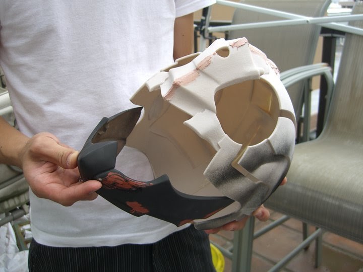
The 3D model was printed on the ZPrinter 450 in parts. We created the lower jaw separately to allow the helmet to be worn and retain a tight fit on the wearer's head. We finished the 3D printed helmet prototype with ZMax to provide extra strength to the helmet so it could be used as a true functional part in production work. Finally, we assembled the helmet and prepared the surface for gloss painting.


Rider Helmet prototype emerging from ZPrinter.


Test Fitting the Jaw

Fit adjustments for the faceplate.

Test fitting the jaw.


Painting the 3D Printed Helmet
We kept to the original color scheme of the character as much as possible. The original Kamen Rider V3 had a grey lower jaw. We opted for silver because we thought it would match the mechanical aspect of our design better. We also selected darker colors to give the character a more mature and contemporary feel. The helmet was painted in layers and sections.


Applying Bondo to the prototype.


First coat of primer and spot patching for the faceplate and jaw.


"Rider CRD" in his first coat of sanded-down primer.


Smoothing, joint patching for "Rider CRD."


Silver base coat laid down on "Rider CRD" helmet.


Metallic red overcoat going on the helmet.


Rider CRD in red metallic paint.


Casting the Resin Eyes
The Rider eyes were cast in resin. The masters were 3D printed and silicone molds were made. Then we mounted the resin eyes in the helmet.


Rider CRD... green eyes.


Adding Lights and Antenna
We added lights in the back of the eyes in order to give them a glowing effect. Finally the antennae were added to complete the look. Some of the smaller details were created in Z Corp’s ZBuilder Ultra plastic prototyping system and then painted.

Completed, functional 3D Printed Kamen Rider CRD Helmet: "Hmmm...something's missing..."


Next on the list, creating the entire suit?


Wednesday, May 11, 2011

The Role of 3D Printing and Scanning in the Community Development of Automobiles

Today's guest blog is by Scott Harmon, Z Corporation VP of Business Development.

I wanted to take this opportunity to share a very cool webcast about using 3D scanning and 3D printing in custom automotive design. The company is called Local Motors. There are a lot of companies out there that make short run replica cars, like Factory Five and ERA Replica Automobiles. These cars are very cool, and people buy thousands of them every year.

Local Motors' approach is very different. Instead making a replica, they’re using a community development model to create a new car. Their design community creates the concept for the car, and the Local Motors' team designs and fabricates it. In the detailed design and fabrication process, they determine how to integrate mass manufactured components and custom designed components. It’s a fascinating combination of re-engineering the as-built parts, and designing entirely new components. The combination is completely novel, and thanks to some smart engineers and some great tools, Local Motors can do it at a price that’s less than many stock cars.

Obviously 3D scanning and 3D printing are critical enabling technologies for these processes, and it’s no surprise that Local Motors uses ZScanning and ZPrinting to quickly and efficiently create an entirely new kind of car. The webcast goes into more detail about how they make cars and the tools they use.

Please let me know what you think of the webcast, if you have questions or want more information.

http://www.zcorp.com

Wednesday, May 4, 2011

3D Printed Trebuchet

This week’s blog is by Nick Stone, Z Corp. Project Leader, Mechanical Engineering, Research and Development.


When I was 15, I saw a PBS program on trebuchet’s and decided to build one in my backyard. Honestly, it was disappointing. My trebuchet threw a tennis ball about 10 feet and sliced a trench into our lawn.

I always wanted to give it another try, so I decided to 3D print a fully-functional trebuchet. I printed all of the parts on a ZPrinter 650. The axels ride in plastic bushing that are used in the ZPrinter 650 feeder assembly. The wheels do turn and are supposed to give you a little extra push. I found a video from the History Channel which provided some good advice on relative lengths, as well as a good way to hang the sling. The length of the string controls the release point as does the weight of the projectile. The heavier the projectile, the earlier the release, and thus the higher the angle. I’m not sure if this is typical of all trebuchets or unique to my sling.

Fully-functional trebuchet 3D printed on a ZPrinter 650

I’ve been threatening one of my fellow engineers, Guy, with my trebuchet since I started designing it. He finally had enough of my taunts and began ZPrinting his own trebuchet. His is about 20” tall and seems strong enough to launch a baseball a good distance. And so the arms race begins…

I decided that, because I had proven trebuchet technology, and since Guy was still perfecting his trebuchet, I’d be best served by improving my projectiles. I had been launching Delrin balls and drywall anchors, but decided to really strike fear into my enemies/co-workers. We have a low melt temp metal on hand, so I ZPrinted some molds and waxed them. I used a heat gun and hot plate to melt the metal and pour it into my molds.

ZPrinted mold for trebuchet’s metal projectile

A flying spiked metal ball is pretty scary (and dangerous, so here’s my disclaimer: Neither I nor Z Corp recommend you try this; if you do, you do it at your own risk and we cannot be held liable for any adverse results!). If Guy starts mobilizing his trebuchet, I might be forced to hold a demonstration near his cube. Until then, I think it’s enough that he knows I have the capability and am crazy enough to try it.

http://www.zcorp.com