Guest post by Julie Reece, Z Corp.'s Director of Marketing Communications.
Makers of 3D CAD software for digital prototyping sometimes claim that their systems eliminate the need for physical prototypes. However, physical and digital prototyping complement one another. Both should become an integral part of your product-development processes.
In fact, physical prototypes are much in use today because they are essential to creating great designs. Thanks to the speed of 3D printing systems, innovative product developers use more physical prototypes than they did when each prototype was hand crafted, and combine them with digital prototypes to accelerate design.
Digital prototyping tools allow detailed 3D models to be conceived and changed quickly. But computer graphics is no substitute for reality. When combined with additive manufacturing technologies, physical prototypes can be made from digital models quickly and with much less labor than was traditionally required.
Deciding when and how to use physical prototypes in addition to digital prototypes requires knowledge of both digital and physical prototyping methods. Engineering executives and managers need not become additive manufacturing experts. However, they or their designated staff members should familiarize themselves with the various physical prototyping system capabilities, materials, costs, building speeds, and accuracies. With this information, managers will have rational bases for deciding if and when making a physical prototype is more cost effective than analyzing or simulating product behavior with digital prototypes.
Whether you are evaluating physical prototyping technologies in order to purchase a system for your company or employ a service, keep these points in mind:
1. Faster systems with higher throughput to produce multiple models simultaneously are desirable for iterative, conceptual prototypes or visual prototypes that support detailed design, manufacturing engineering, or marketing.
2. If you plan to make many prototypes, low material costs may be more important than buying a low-priced system.
3. Color systems eliminate the need for painting and finishing.
4. Strong but flexible materials may be needed for evaluating snap fits.
5. Some technologies are well suited to making patterns for metal castings while others are not.
6. Higher-strength materials may be necessary for physical testing.
7. Systems with fine surface finish may be required for working prototypes or final advertising shots, but can take longer to produce.
Companies that make wise choices about both digital and physical prototyping technologies will have competitive advantages compared with companies that don’t. The effective combination of both CAD and engineering software with 3D printing and rapid prototyping assures that your company will deliver products that are desirable, affordable, reliable, and safe.
Excerpt of a white paper entitled, “Physical and Digital Prototyping Belong Together,” by L. Stephen Wolfe, P.E. Read the full white paper.
L. Stephen Wolfe, P.E. is a professional mechanical engineer based in San Diego, California. For more than 20 years, he published the newsletters Computer Aided Design Report, Rapid Prototyping Report, and Product Data Management Report as well as books on these topics. These publications filled the role of Consumer Reports for engineers seeking objective information about product-development technologies. He currently assists buyers of CAD/CAM, CAE, PDM, and rapid prototyping systems with defining their requirements, conducting independent research, identifying and negotiating with suppliers, and implementing new methods efficiently. www.cadcampub.com
http://www.zcorp.com

Wednesday, November 17, 2010


Wednesday, November 10, 2010
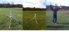
Engineering Challenge

Challenges like this one help our engineers more fully understand the limits and capabilities of our 3DP technology. They provide a creative environment that fosters problem solving and innovation.
Wednesday, November 3, 2010
Iterative Design - As Easy As 1, 2, 3D Print
This week’s guest post is by Leo Kiefer, Z Corporation Mechanical Engineer
I found a good definition on Wikipedia.org the other day:
Iterative design is a design methodology based on a cyclic process of prototyping, testing, analyzing, and refining a product or process.
This could not have described my recent design exercise better.
In an effort to minimize the number of molded parts on a particular 3D printer, I was tasked with the redesign of one of the service stations used in this printer. During the printing process, powder and binder gradually build up on the face of the print head. The role of this particular station is to keep print heads clean by periodically “servicing” or removing the build-up. It is a simple, yet important, process that requires the print head assembly to push down on a spring-loaded cam, set the correct height, and then slide along the cam to perform the proper cleaning procedure.
I was able to consolidate the design into a single injection molded part. I wanted to print a prototype to ensure the design was correct before investing in a molding tool. Due to some design limitations for molding, I was not able to achieve a tight interface between this base part and my cam part. This caused the parts to bind, and not return to their original position in certain scenarios.

After some testing and analyzing the cam action, I decided to change the interface to a 2-post and 2-collar design. Essentially the posts would act as guides for 2 collars on the cam part. Since I no longer had to deal with tooling shut-offs in the interface areas, I was able to minimize the draft angles and reduce the amount of clearance between the parts. I retained the single base part requirement, but had to add 2 plastic screws in exchange.
So I printed another model on our ZPrinter® 650. The new iteration did achieve a slight performance increase, but not enough. So, back to the drawing board. I decided to move the bosses further apart, assuming that wider is better, and quickly made yet another 3D printed model. This time I almost had it, but I wanted to make a small tweak in order to get it to be 100% perfect. The binding was completely eliminated in the back to forth direction, yet it still caused problems left to right. Instead of increasing the clearance between my boss and sleeve, I decided to make the holes slightly oval in the left to right direction. Another 3D printed model fresh from the printer proved to have all the requirements I was looking for.

Admittedly CAD software is a good tool for getting parts to fit together, but when it comes to moving components, nothing beats a good physical prototype. The whole design process could have taken a single day if that was all I was working on, but I was able to cut considerable time off the design process by 3D printing models along the way, versus machining the prototypes. With the help of a ZPrinter, the Iterative Design process is a fast and extremely useful tool in any designer’s bag of tricks.

CAD Software: SolidWorks 2010
Printed On: ZPrinter® 650 using zp150 powder
Print Job: 432 layers, approx 2.5hrs
http://www.zcorp.com/
I found a good definition on Wikipedia.org the other day:
Iterative design is a design methodology based on a cyclic process of prototyping, testing, analyzing, and refining a product or process.
This could not have described my recent design exercise better.
In an effort to minimize the number of molded parts on a particular 3D printer, I was tasked with the redesign of one of the service stations used in this printer. During the printing process, powder and binder gradually build up on the face of the print head. The role of this particular station is to keep print heads clean by periodically “servicing” or removing the build-up. It is a simple, yet important, process that requires the print head assembly to push down on a spring-loaded cam, set the correct height, and then slide along the cam to perform the proper cleaning procedure.
I was able to consolidate the design into a single injection molded part. I wanted to print a prototype to ensure the design was correct before investing in a molding tool. Due to some design limitations for molding, I was not able to achieve a tight interface between this base part and my cam part. This caused the parts to bind, and not return to their original position in certain scenarios.

Figure 1 - Original model - Shown exhibiting the racking problem and without the rubber wiper.
After some testing and analyzing the cam action, I decided to change the interface to a 2-post and 2-collar design. Essentially the posts would act as guides for 2 collars on the cam part. Since I no longer had to deal with tooling shut-offs in the interface areas, I was able to minimize the draft angles and reduce the amount of clearance between the parts. I retained the single base part requirement, but had to add 2 plastic screws in exchange.
So I printed another model on our ZPrinter® 650. The new iteration did achieve a slight performance increase, but not enough. So, back to the drawing board. I decided to move the bosses further apart, assuming that wider is better, and quickly made yet another 3D printed model. This time I almost had it, but I wanted to make a small tweak in order to get it to be 100% perfect. The binding was completely eliminated in the back to forth direction, yet it still caused problems left to right. Instead of increasing the clearance between my boss and sleeve, I decided to make the holes slightly oval in the left to right direction. Another 3D printed model fresh from the printer proved to have all the requirements I was looking for.
Figure 2 – Cross-sectioned SolidWorks CAD model of final assembly
Admittedly CAD software is a good tool for getting parts to fit together, but when it comes to moving components, nothing beats a good physical prototype. The whole design process could have taken a single day if that was all I was working on, but I was able to cut considerable time off the design process by 3D printing models along the way, versus machining the prototypes. With the help of a ZPrinter, the Iterative Design process is a fast and extremely useful tool in any designer’s bag of tricks.

Figure 3 – Iterative Design summarized in one image
CAD Software: SolidWorks 2010
Printed On: ZPrinter® 650 using zp150 powder
Print Job: 432 layers, approx 2.5hrs
http://www.zcorp.com/
Wednesday, October 27, 2010
Considering Feature Set Value in the Product Development Process
I spend a lot of time thinking about how to enhance our ZPrinter® product line in ways that truly add value to the end user. In fact, when I think about the end user I consider both the person using the printer and the person in need of the printed model. Of course there are other stakeholders but none are impacted by a feature enhancement more than those two. The person who needs the part might be more interested in how fast he can have his model, how accurate the part is, or maybe how close the model’s material properties are to the intended material of the production part. On the other hand, the person running the printer is probably more concerned with ease of use features, such as auto-alignment, cartridge loading, and comfort and visibility while interfacing with the printer.
The design challenge is that often in order to improve one feature, another is impacted. Let me give you a hypothetical example: we might be striving to improve part accuracy, but doing so might slow the print speed. In order to make that decision, we have to understand how to measure the value of further improved part accuracy against reducing print speed to the end user. I would think about this problem in the same way we approach our own product development process where making a single change in a late stage of the process is far more costly than frequent changes in the early stages. Using 3D printing early and often can not only reduce the risk of late stage changes, but will often lead to better decision making and reduced overall cost of development programs. So feature set enhancements that allow for more iterations in the same amount of time and for the same cost are feature sets that add real value.
It doesn’t stop there though. In my example, having more models in the early design stage improves decision making by improving the way the design is communicated. Therefore feature set enhancements that improve the model as a means of communication also add significant value. It is well known that our color printers can be used to create life-like models. Consumer products can be modeled in the intended color combinations or with graphics printed right on the part. Often overlooked is the ability to label models with part and revision numbers or by color coding differences between on model and another, all with the intent to improve and speed up the decision making process.


My question this week is, do you agree with my assessment of value? What do you value in 3DP?
Related reading in Develop3D: http://develop3d.com/profiles/prints-charming
http://www.zcorp.com/
The design challenge is that often in order to improve one feature, another is impacted. Let me give you a hypothetical example: we might be striving to improve part accuracy, but doing so might slow the print speed. In order to make that decision, we have to understand how to measure the value of further improved part accuracy against reducing print speed to the end user. I would think about this problem in the same way we approach our own product development process where making a single change in a late stage of the process is far more costly than frequent changes in the early stages. Using 3D printing early and often can not only reduce the risk of late stage changes, but will often lead to better decision making and reduced overall cost of development programs. So feature set enhancements that allow for more iterations in the same amount of time and for the same cost are feature sets that add real value.
It doesn’t stop there though. In my example, having more models in the early design stage improves decision making by improving the way the design is communicated. Therefore feature set enhancements that improve the model as a means of communication also add significant value. It is well known that our color printers can be used to create life-like models. Consumer products can be modeled in the intended color combinations or with graphics printed right on the part. Often overlooked is the ability to label models with part and revision numbers or by color coding differences between on model and another, all with the intent to improve and speed up the decision making process.


My question this week is, do you agree with my assessment of value? What do you value in 3DP?
Related reading in Develop3D: http://develop3d.com/profiles/prints-charming
http://www.zcorp.com/
Wednesday, October 20, 2010
Extraordinary 3D Printing
The recent blog written by Z Corp.’s firmware engineer Andrew Berlin about how he used 3D printing in a non-traditional way to encode information generated a great deal of interest. I think that is fantastic and I am grateful that Andy took the time to write about his efforts. I thought you might want to see a brief video of the ZPrinted record album working. We are working on an audio file, but in the meantime, enjoy the short video.
The level of interest his blog generated got me wondering about other “out of the ordinary” ways that 3D printing is being used. For example, there is Enrico Dini who was featured in Popular Science magazine. He believes that someday entire buildings will be “printed.” For now, he is creating large intricate architectural elements that could not have otherwise been created: http://www.blueprintmagazine.co.uk/index.php/architecture/the-worlds-first-printed-building/.
There is also the work being done in Bio-fabrication by Thomas Boland of the University of Texas, Paul Calvert of U Mass. Dartmouth and others. This is a fascinating and diverse field of studies that includes printing biological materials in order to create 3D living tissues. An Internet search will result in pages similar to the following. http://iopscience.iop.org/1758-5090/2/1/010201/pdf/1758-5090_2_1_010201.pdf. This is very far removed from a typical design cycle where 3D printing is commonly used. If successful, this work could lead to 3D printers designed specifically for “building” human organs!
Another example outside the norm is Pixar’s Toy Story Zeotrope. The full color Spectrum Z™510 made this project possible. Because the Toy Story characters were digitally created they were “trapped” inside the computer. Without 3D printing it would not have been possible to accurately translate them from virtual to actual characters. Click the following link for a description of the Zeotrope: http://www.youtube.com/watch?v=ByimDfnq_Fg and click the following link for a higher resolution video of the Zeotrope in action: http://www.youtube.com/watch?v=nKPtmXK--bA&feature=related.
Also check out this YouTube video of two artists who make musical instruments from ZPrinted parts. Audio files and even a music video are currently in development and will be posted when they’re complete.
(Courtesy Elasticbrand [Christie Wright & Arjen Noordeman]
Project: AudioWear
Music by Skooby Laposky
Produced at the new EKWC (European Ceramic Work Centre) CAD/CAM facility, August - September 2010
So, from architectural structures to bio-fabrication to digital arts, new uses for 3D printing are being explored every day. Some are whimsical and some may have very practical applications. Regardless of their utility, what they all have in common is that they have been made possible by 3D printing technologies.
Do you have an interesting, creative use for 3D printers? Let me know about it and I just might feature you here.
http://www.zcorp.com/
The level of interest his blog generated got me wondering about other “out of the ordinary” ways that 3D printing is being used. For example, there is Enrico Dini who was featured in Popular Science magazine. He believes that someday entire buildings will be “printed.” For now, he is creating large intricate architectural elements that could not have otherwise been created: http://www.blueprintmagazine.co.uk/index.php/architecture/the-worlds-first-printed-building/.
There is also the work being done in Bio-fabrication by Thomas Boland of the University of Texas, Paul Calvert of U Mass. Dartmouth and others. This is a fascinating and diverse field of studies that includes printing biological materials in order to create 3D living tissues. An Internet search will result in pages similar to the following. http://iopscience.iop.org/1758-5090/2/1/010201/pdf/1758-5090_2_1_010201.pdf. This is very far removed from a typical design cycle where 3D printing is commonly used. If successful, this work could lead to 3D printers designed specifically for “building” human organs!
Another example outside the norm is Pixar’s Toy Story Zeotrope. The full color Spectrum Z™510 made this project possible. Because the Toy Story characters were digitally created they were “trapped” inside the computer. Without 3D printing it would not have been possible to accurately translate them from virtual to actual characters. Click the following link for a description of the Zeotrope: http://www.youtube.com/watch?v=ByimDfnq_Fg and click the following link for a higher resolution video of the Zeotrope in action: http://www.youtube.com/watch?v=nKPtmXK--bA&feature=related.
Also check out this YouTube video of two artists who make musical instruments from ZPrinted parts. Audio files and even a music video are currently in development and will be posted when they’re complete.
(Courtesy Elasticbrand [Christie Wright & Arjen Noordeman]
Project: AudioWear
Music by Skooby Laposky
Produced at the new EKWC (European Ceramic Work Centre) CAD/CAM facility, August - September 2010
So, from architectural structures to bio-fabrication to digital arts, new uses for 3D printing are being explored every day. Some are whimsical and some may have very practical applications. Regardless of their utility, what they all have in common is that they have been made possible by 3D printing technologies.
Do you have an interesting, creative use for 3D printers? Let me know about it and I just might feature you here.
http://www.zcorp.com/
Wednesday, October 13, 2010
ZScanning Any Object at Any Resolution With ZScan 5.0
Today's guest post by Julie Reece, Z Corporation Director of Marketing Communications
Today Z Corporation announced a powerful 3D scanning software upgrade that makes using our ZScanner® handheld 3D laser scanners even faster and easier than ever.
What does the new ZScan® 5.0 release (available October 20) mean for you? In a nutshell:
• Scan any size at any resolution within the scanner’s range; no more restraining bonding box
• Merge scans in a single accurate and optimized mesh without any post-treatment
• See your entire 3D surface in real time
• Fill holes, filter boundaries, decimate your model and much more!
Scan any part at any resolution, within the scanners’ range, without any limitations due to part size.
In a word: no more scanning volume. As you can see in the image below, the only parameter that you need to choose is the resolution of your scan. Once you select your resolution, you're ready to scan.


Automatic hole filling.
Filling holes is controlled with a slider in the facets node, just like the decimate triangles or remove isolated patches slider. This tool focuses on smaller holes that can be filled easily and automatically, and does not offer an interactive mode. It eliminates the time-consuming job of cleaning STL files.
Automatic hole filling also accounts for the texture of the scanned object (with the ZScanner® 700 CX) which was scanned but not projected onto the surface. It does not interpolate the texture. Rather, it applies the object’s texture onto the filled hole. The other holes will appear grey, similar to when you scan without the texture of the ZScanner® 700 CX.


• EXPERIENCE tools that are changing the way companies design, engineer and manufacture – faster, better, greener, more customized.
• INTERACT with Geomagic developers, expert users and your peers who are breaking down barriers to productivity, innovation and customer satisfaction.
• IMMERSE yourself in the new features of Geomagic Studio 12 and Geomagic Qualify 12 with exclusive training sessions and live demos.
• TAKE AWAY information, contacts and knowledge that will help deliver you to points beyond your competitors.
Today Z Corporation announced a powerful 3D scanning software upgrade that makes using our ZScanner® handheld 3D laser scanners even faster and easier than ever.
What does the new ZScan® 5.0 release (available October 20) mean for you? In a nutshell:
• Scan any size at any resolution within the scanner’s range; no more restraining bonding box
• Merge scans in a single accurate and optimized mesh without any post-treatment
• See your entire 3D surface in real time
• Fill holes, filter boundaries, decimate your model and much more!
Scan any part at any resolution, within the scanners’ range, without any limitations due to part size.
In a word: no more scanning volume. As you can see in the image below, the only parameter that you need to choose is the resolution of your scan. Once you select your resolution, you're ready to scan.
For you scanning volume junkies, this option is still available through the Use Manual Reconstruction Volume checkbox. This option also enables clipping planes.
A user or multiple users can merge scans and reconstruct surfaces using different session files.This interface is used to merge different scans which have been scanned in the same reference model. This is particularly useful when multiple scanners are used for the same scan or when individual session files are too large for the computer on which the scan is located.
It is important to note that the merge of the scans is made on the raw data, so it's not merely stitching STL files. There is no boundary between the different scans and you still benefit from the powerful surface reconstruction algorithms from ZScan® 5.0.Automatic hole filling.
Filling holes is controlled with a slider in the facets node, just like the decimate triangles or remove isolated patches slider. This tool focuses on smaller holes that can be filled easily and automatically, and does not offer an interactive mode. It eliminates the time-consuming job of cleaning STL files.
Automatic hole filling also accounts for the texture of the scanned object (with the ZScanner® 700 CX) which was scanned but not projected onto the surface. It does not interpolate the texture. Rather, it applies the object’s texture onto the filled hole. The other holes will appear grey, similar to when you scan without the texture of the ZScanner® 700 CX.
To read today’s ZScan 5.0 press release.
Also, be sure to register for Geomagic’s Points Beyond Tour, free, worldwide conference, training and networking event.
• INTERACT with Geomagic developers, expert users and your peers who are breaking down barriers to productivity, innovation and customer satisfaction.
• IMMERSE yourself in the new features of Geomagic Studio 12 and Geomagic Qualify 12 with exclusive training sessions and live demos.
• TAKE AWAY information, contacts and knowledge that will help deliver you to points beyond your competitors.
Wednesday, October 6, 2010
Timber House
One of the things I love about working here at Z Corp. is when I am able to help someone discover the unique capabilities of 3D printing, specifically how ZPrinting can help solve real problems.
A few weeks back I ran into an old friend, during a wine tasting event at a local vineyard, who I had not seen in many years. As is often the case during these chance meetings, we both talked at length about what we had been up to over the past few years. The last time I saw him I must have just recently started my career at Z Corp. because he seemed to remember me telling him something about models. My friend is a local architect specializing in high-end custom homes.
Like many individual or small firm architects that have been around for a while, this guy hand draws most of his concepts and many of his detail drawings. His early design decision process involves sketching concepts, reviewing them with the customer, and re-sketching until they both agree on what is to be built. This is time consuming and at the end to the day there is always a risk that the sketch did not accurately represent the final building. How close the end product is to what is expected depends upon the quality of the sketches, as well as the customers’ ability to interpret them or to visualize the final building from the sketches.
Recently some of the younger architects working with my friend started using 3D software to turn early concepts into more realistic renderings in an effort to better communicate and make decisions at this early design stage. As luck would have it, they were in the midst of a project with a client where the husband was in the building profession and, because of his experience, could easily interpret drawings. The husband and wife were in disagreement about a particular detail - whether an entire wall in their new great room should be made of stone or just the section above the fireplace. The architect had rendered the room and shown them the renderings on the computer screen, but a decision had yet to be made.
I offered to take the 3D data from their software and print a model for their next client meeting on the following Thursday. I was able to export the 3D data, including texture map images for the wood, stone and other surfaces. I delivered the completed ¼” scale model in full color on Wednesday afternoon. My friend was amazed, his client was amazed, and I was very happy to help. The husband was finally convinced that his wife was right. Through a chance meeting at a local vineyard, I was able to help a friend solve a real issue by improving communication using Z Corp. 3D printing technology.
Click here and scroll to the bottom of the page to see a sampling of ZPrinted architectural models.
A few weeks back I ran into an old friend, during a wine tasting event at a local vineyard, who I had not seen in many years. As is often the case during these chance meetings, we both talked at length about what we had been up to over the past few years. The last time I saw him I must have just recently started my career at Z Corp. because he seemed to remember me telling him something about models. My friend is a local architect specializing in high-end custom homes.
Like many individual or small firm architects that have been around for a while, this guy hand draws most of his concepts and many of his detail drawings. His early design decision process involves sketching concepts, reviewing them with the customer, and re-sketching until they both agree on what is to be built. This is time consuming and at the end to the day there is always a risk that the sketch did not accurately represent the final building. How close the end product is to what is expected depends upon the quality of the sketches, as well as the customers’ ability to interpret them or to visualize the final building from the sketches.
Recently some of the younger architects working with my friend started using 3D software to turn early concepts into more realistic renderings in an effort to better communicate and make decisions at this early design stage. As luck would have it, they were in the midst of a project with a client where the husband was in the building profession and, because of his experience, could easily interpret drawings. The husband and wife were in disagreement about a particular detail - whether an entire wall in their new great room should be made of stone or just the section above the fireplace. The architect had rendered the room and shown them the renderings on the computer screen, but a decision had yet to be made.
I offered to take the 3D data from their software and print a model for their next client meeting on the following Thursday. I was able to export the 3D data, including texture map images for the wood, stone and other surfaces. I delivered the completed ¼” scale model in full color on Wednesday afternoon. My friend was amazed, his client was amazed, and I was very happy to help. The husband was finally convinced that his wife was right. Through a chance meeting at a local vineyard, I was able to help a friend solve a real issue by improving communication using Z Corp. 3D printing technology.
Click here and scroll to the bottom of the page to see a sampling of ZPrinted architectural models.
Subscribe to:
Posts (Atom)
Scott Harmon

Subscribe To


 Posts
All Comments
Posts
All Comments